Quick answer
Single-mode fiber (OS2) has a 9 µm core and reaches 10 km or more at 10G; multimode (OM3/OM4/OM5) has a 50 µm core and stops at 300–400 m at 10G per IEEE 802.3. Choose multimode for short in-room runs where cheaper optics are already installed, single-mode for anything longer or meant to outlast the next speed upgrade. Kestner builds and loss-tests both.
The short version
- The grade is set by the core: 9 µm single-mode (OS2) carries one light path over kilometers; 50 µm multimode (OM3/OM4/OM5) carries many paths over a few hundred meters.
- At 10G, IEEE 802.3 gives OM3 300 m, OM4 and OM5 400 m, and OS2 10 km (40 km with ER optics). At 25G the multimode numbers fall to 70 m and 100 m.
- The cable is a small share of link cost; the optics are most of it. Match the fiber to the transceivers you already run, then to how long the cabling must last.
- OM5 only earns its premium if you run wavelength-multiplexed (SWDM) multimode optics. For plain 850 nm links it behaves like OM4.
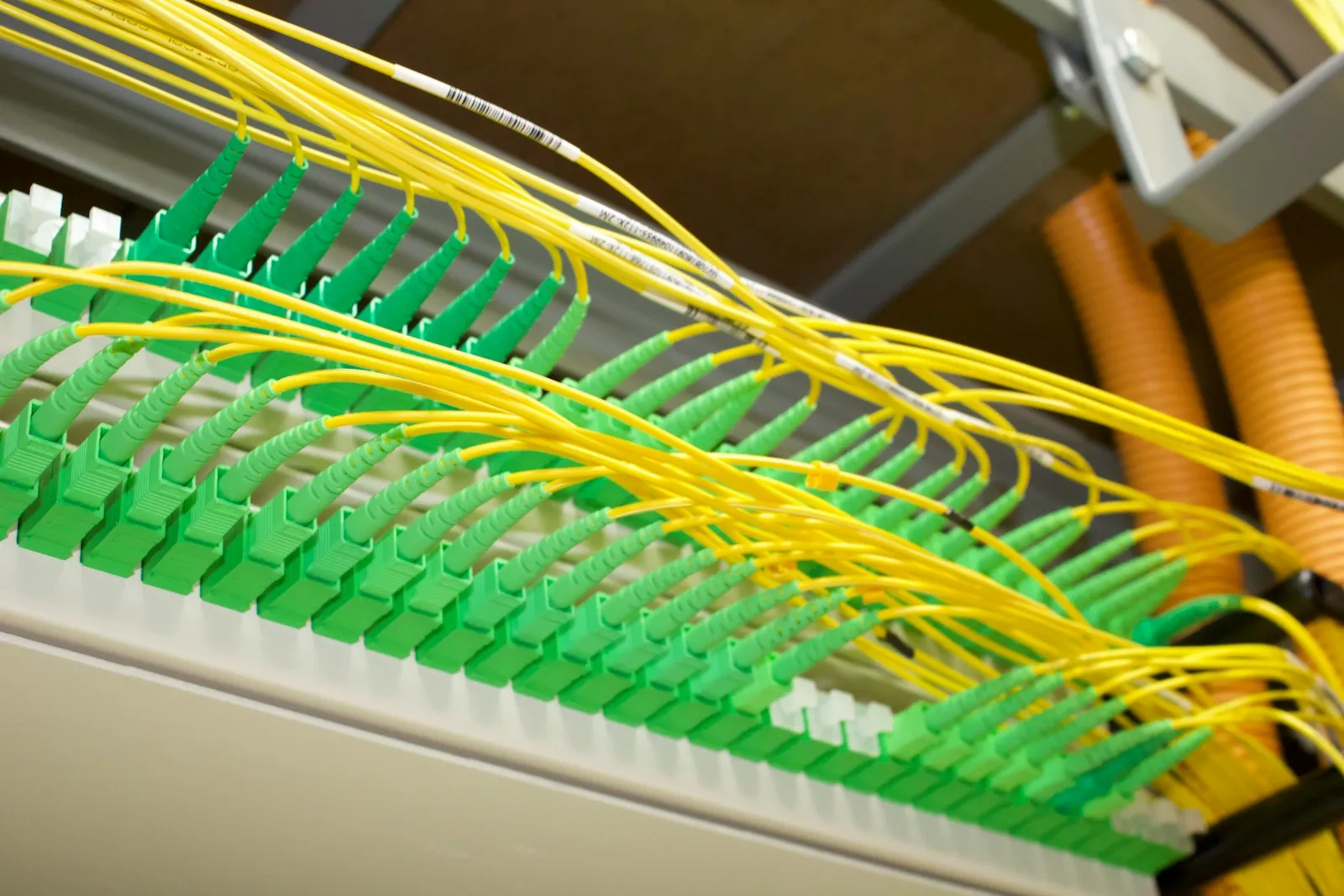
- Jacket colors are a free receiving check: yellow = single-mode, aqua = OM3/OM4, lime = OM5, orange = legacy OM1/OM2. Never cross-mate a green APC with a blue UPC.
Single-mode or multimode is the first line on any fiber order, and the one that is hardest to undo: the cable, the connectors, and the transceivers on both ends all have to agree. The short version is that single-mode (OS2) goes far and multimode (OM3, OM4, OM5) goes short, but that alone does not tell a buyer what to order. What matters is how far each grade actually reaches at the speed you run, where the money in a link really goes, and the few spec lines that stop the wrong cord from arriving. That is what this guide covers.
The difference in one table
BLUF: the core decides everything. A 9 µm single-mode core carries one path of light and reaches kilometers. A 50 µm multimode core carries many paths, and the spread between them (modal dispersion) caps reach at a few hundred meters once speeds climb.
| OS2 single-mode | OM3 multimode | OM4 multimode | OM5 multimode | |
|---|---|---|---|---|
| Core / cladding | 9 / 125 µm | 50 / 125 µm | 50 / 125 µm | 50 / 125 µm |
| Light source | 1310 / 1550 nm laser | 850 nm VCSEL | 850 nm VCSEL | 850–953 nm VCSEL |
| Bandwidth (EMB, 850 nm) | n/a | 2,000 MHz·km | 4,700 MHz·km | 4,700 MHz·km |
| Reach at 10G | 10 km (LR), 40 km (ER) | 300 m | 400 m | 400 m |
| Reach at 25G | 10 km (LR) | 70 m | 100 m | 100 m |
| Jacket color | Yellow | Aqua | Aqua (sometimes violet) | Lime green |
| Typical use | Campus, building backbone, carrier, new data-center builds | Legacy in-room runs | Default for new multimode | SWDM multimode links |
Reach figures are the IEEE 802.3 distances for 10GBASE-SR/LR/ER and 25GBASE-SR/LR. Bandwidth is the TIA-492 effective modal bandwidth for each grade. Colors follow TIA-598-D. Legacy OM1 (62.5 µm) and OM2 are orange and reach only 33 m and 82 m at 10G; do not specify them for new work.
If you remember one row, make it reach at the speed you actually run. A multimode link that worked at 10G can fail when the same run is moved to 25G optics, because the distance limit drops by roughly three quarters.
Where the money in a link goes
BLUF: the fiber is the cheap part. On a short link, the transceivers on each end cost far more than the patch cord between them, so choose the fiber to match the optics you run, then to how long the cabling has to last.
That is the real reason multimode exists. Multimode optics use 850 nm VCSELs, which have long been cheaper to build than the lasers single-mode needs. For runs inside one room, cheaper optics more than paid for themselves, and the extra reach of single-mode bought nothing. Three things have changed the math since:
- Speeds keep cutting multimode reach. Every jump (10G to 25G to 100G per lane) shortens what OM3 and OM4 can carry. Single-mode reach barely moves.
- Single-mode optics are now made in volume. Large data-center operators standardized on single-mode, and the price gap to multimode optics narrowed as a result.
- Cabling outlives optics. Fiber in the walls and trays usually stays through several transceiver generations. Re-pulling cable costs more than any patch cord saving.
The practical rule we give buyers: if a run is short, stays in one room, and the switch ports already take SR optics, buy OM4. If the run crosses floors or buildings, or the plant has to carry the next speed upgrade, buy OS2. Do not choose the grade by comparing the price of the cords.
OM3 vs OM4 vs OM5
BLUF: OM4 is the default for new multimode. OM3 is fine for matching an existing plant. OM5 only pays if you run SWDM optics.
OM3 and OM4 are both 50 µm, laser-optimized multimode; the difference is bandwidth. OM4 carries more than twice the effective modal bandwidth (4,700 vs 2,000 MHz·km at 850 nm), which shows up as longer reach on the same optics: 400 m vs 300 m at 10G, and 100 m vs 70 m at 25G. Since the cords cost about the same, there is rarely a reason to start a new run on OM3. The exception is extending an existing OM3 plant, where the link only performs to its weakest segment anyway.
OM5 (TIA-492AAAE) is specified across 850 to 953 nm so a single fiber can carry several wavelengths at once. That matters for short-wavelength-division-multiplexing (SWDM) transceivers, and nothing else. At a single 850 nm wavelength, OM5 performs like OM4. If the optics on both ends are standard SR parts, OM5 is a premium for capability you will not use. Ask which transceivers the link will run before you accept it on a quote.
UPC vs APC, LC vs SC
BLUF: the connector has to match the port, and the polish has to match the mating connector. Get either wrong and the link either will not seat or will not pass loss.
Polish. Single-mode connectors come in two polishes. UPC (ultra physical contact) is polished to a slight dome and typically holds about 50 dB return loss; its housing is blue. APC (angled physical contact) is polished at 8 degrees so reflected light is sent out of the core, holding 60 dB or better; its housing is green. APC is standard where reflections hurt, such as FTTx, video, and long-haul carrier links. UPC is standard on most data-center switch optics. Multimode connectors are UPC/PC only.
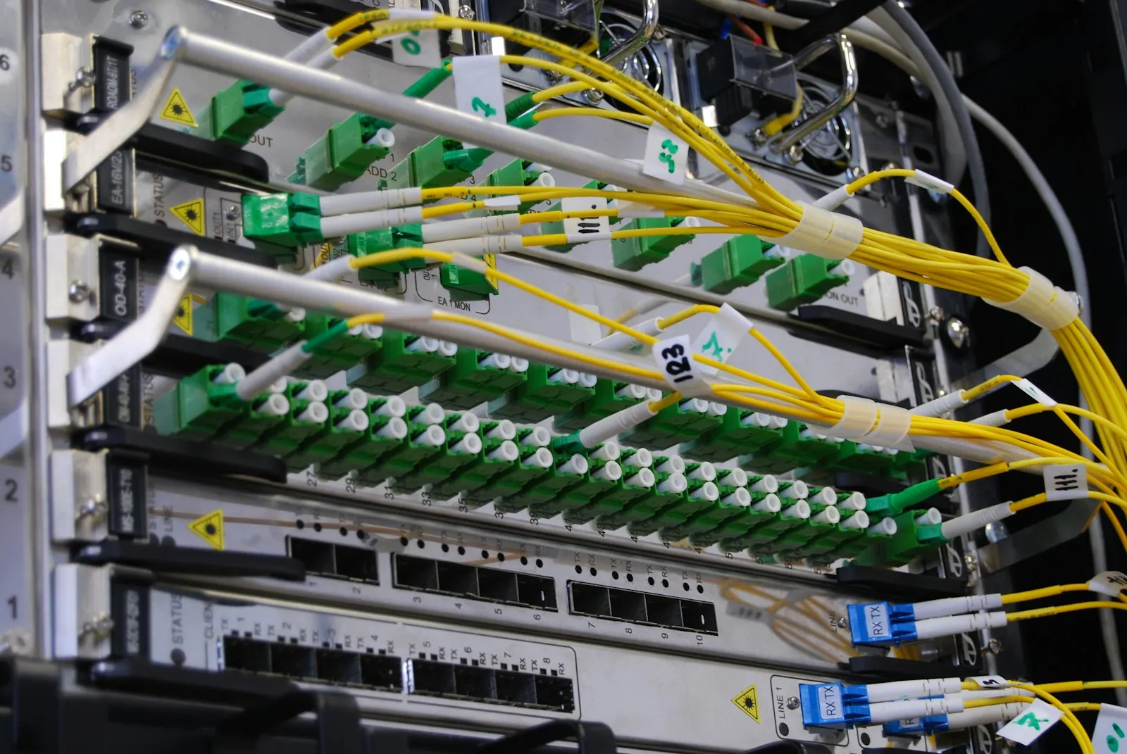
Never mate an APC connector to a UPC one. The angled and flat endfaces touch only at an edge, the air gap throws loss far out of spec, and the pressure can chip both ferrules. A single mismated jumper in a patch panel can look plugged in and still fail a link test.
Connector. LC is the small-form-factor connector with a 1.25 mm ferrule. It is what SFP and QSFP duplex transceivers take, and it is the default in data centers because it packs twice as many ports per panel. SC uses a 2.5 mm ferrule, is push-pull and easy to handle, and remains common in carrier, FTTx, and older enterprise panels. ST is a bayonet-lock legacy connector still found in campus and industrial plants. Order by what is on the equipment, not by preference: an LC-to-SC hybrid cord is a normal part when a switch meets an older panel.
What to put on the PO
BLUF: a fiber patch cord is fully defined by seven lines. Leave any one off and the supplier fills it in for you.
| Spec line | What to write | Why it matters |
|---|---|---|
| Fiber grade | OS2 (G.652.D), or OM3 / OM4 / OM5 | Must match the transceivers and the rest of the link |
| Connectors, each end | LC, SC, or ST; simplex or duplex | Must match the port on each end, which may differ |
| Polish | UPC or APC, per end | APC and UPC cannot be mated |
| Length | Measured run plus slack, in meters | Too short will not reach; too long becomes coils that break the bend radius |
| Jacket rating | OFNP (plenum), OFNR (riser), or LSZH | Set by building code for the space the cord passes through |
| Bend performance | Bend-insensitive (G.657.A1/A2) for tight patching | Dense panels bend cords tighter than standard fiber tolerates |
| Test data | Insertion and return loss per cord; endface inspection to IEC 61300-3-35 | Proves the cord you received, not a datasheet typical |
For context on the loss line: TIA-568.3-D allows up to 0.75 dB per mated connector pair in a link budget. A good factory-terminated cord tests well below that, which is the margin you want, because every patch point in a channel spends part of the budget. Ask for the measured number per cord, keyed to a serial or label, not a statement that the cords “meet TIA.”
Which should you buy
Start from the optics and the run, not the cable. If the run is short, stays in one room, and the ports already take SR optics, OM4 multimode is the economical choice; OM5 only if you run SWDM optics. If the run crosses floors or buildings, feeds a carrier or campus link, or has to carry the next speed generation, OS2 single-mode is the safer spend. Then lock the polish, connectors, length, jacket rating, and a per-cord loss result on the PO. For who should build it, see how to choose a fiber optic cable manufacturer; for assemblies beyond a patch cord, the custom fiber assembly guide covers the rest. When you are ready to order, send us the run: the optics on each end and the length, and we will quote the grade the link needs, built and loss-tested, with the patch cord options to match.
Frequently asked
What is the difference between single-mode and multimode fiber?
Core size and light source. Single-mode fiber has a 9 µm core that carries one mode of light from a 1310 or 1550 nm laser, so it reaches 10 km or more. Multimode fiber has a 50 µm (or legacy 62.5 µm) core that carries many modes from an 850 nm VCSEL, so modal dispersion limits it to a few hundred meters at 10G and above.
Can you mix single-mode and multimode fiber?
No. Light from a 50 µm multimode core cannot couple into a 9 µm single-mode core without very large loss, and the transceivers on each end are built for one fiber type. The only planned exception is the mode-conditioning patch cord, a legacy part for running 1000BASE-LX single-mode optics over installed multimode. For new work, keep each link one fiber type end to end.
How do I know if my fiber is single-mode or multimode?
Read the jacket print first: it states the fiber type (9/125 or OS2 for single-mode; 50/125 with OM3, OM4, or OM5 for multimode). The jacket color is a quick second check under TIA-598: yellow for single-mode, aqua for OM3/OM4, lime green for OM5, orange for older OM1/OM2. Transceiver labels also state SR (multimode) or LR/ER (single-mode).
What is the difference between OM3 and OM4?
Both are 50 µm laser-optimized multimode, but OM4 has more than twice the effective modal bandwidth (4,700 vs 2,000 MHz·km at 850 nm). In practice that means longer reach on the same optics: 400 m vs 300 m at 10G, and 100 m vs 70 m at 25G. Pricing is close, so OM4 is the usual default for new multimode runs.
Is OM5 better than OM4?
Only if you use short-wavelength-division-multiplexing (SWDM) optics. OM5 is specified across 850–953 nm so it can carry several wavelengths per fiber; at a single 850 nm wavelength it performs like OM4. If your transceivers are standard SR optics, OM5 costs more and buys nothing.
What are the disadvantages of single-mode fiber?
Historically, optics cost: single-mode lasers cost more than multimode VCSELs, and on short runs that dominated the link budget. The gap has narrowed as single-mode optics shipped in volume for large data centers. Single-mode connectors are also less forgiving of dirt and polish defects because the core is smaller, so endface inspection and loss testing matter more.
What is the difference between UPC and APC?
Both are single-mode connector polishes. UPC is polished flat-domed and typically holds about 50 dB return loss; APC is angled at 8 degrees so reflected light leaves the core, holding 60 dB or better. APC connectors are green, UPC single-mode are blue. They cannot be mated to each other without damage and high loss.
Sources
- IEEE 802.3, Ethernet physical layers (10GBASE-SR/LR/ER, 25GBASE-SR reach)IEEE Standards Association
- ANSI/TIA-568.3-D, optical fiber cabling and components (connector loss)TIA
- TIA-492AAAC / AAAD / AAAE, OM3, OM4, OM5 multimode fiber bandwidthTIA
- TIA-598-D, optical fiber cable color codingTIA
- ITU-T G.652, single-mode optical fiber characteristicsITU
- IEC 61300-3-35, fiber optic connector endface inspectionIEC
More in this cluster
Products in this line
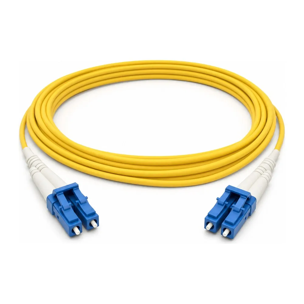 Data-center fiber & patch cableOS2 single-mode and OM3/OM4/OM5 multimode LC, SC, and ST patch cords in UPC or APC, built to length, insertion- and return-loss tested, origin-documented.View →
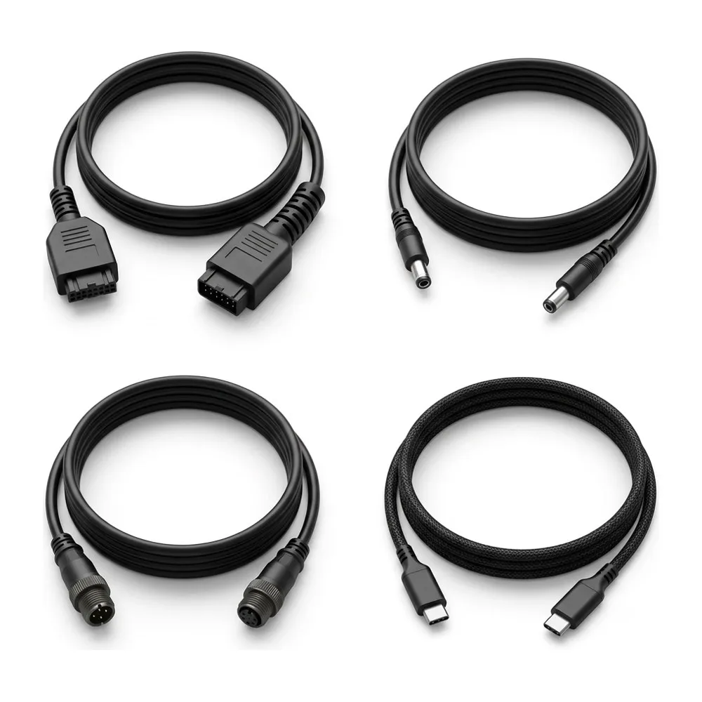 Custom cable assembliesCopper and hybrid assemblies to your drawing, with the termination method specified and the origin paper that survives entry.View →
Ready to source this to spec?
Kestner terminates and tests OS2 single-mode and OM3/OM4/OM5 multimode patch cords on its own lines: LC, SC, or ST, UPC or APC, to your length and jacket rating, with an insertion- and return-loss result for every cord and the country-of-origin record in hand. Tell us the optics on each end and the run length, and we will quote the right grade, not the most expensive one.
Request a quote